On the cover: Quaternion Julia fractals
If you’re a roboticist or game developer, I’m sure you have worked with these pesky little bastards called quaternions and have broken your head over them just like me. For others who are bit non-mathy, quaternions may sound like one of those things from particle physics. So in this post, I’ll try to explain what I have learnt about these guys and how they are useful in coordinate transformations / body rotations. I hope you’re familiar with some basic matrix manipulations and vector algebra. Brace yourselves :)
Ever worked with complex numbers? If yes, then quaternions are pretty similar. They are essentially a made-up number system by an Irish mathematician, William Rowan Hamilton in 1843 (talk about being jobless, yeesh; just kidding of course). A complex number has two terms: $(x + yi)$ where $x$ is the real part, $y$ is the imaginary part and $i^2 = -1$.
Similarly, a quaternion has four terms: $(w + xi + yj + zk)$ where $w$ is the real part and $x, y, z$ together form the complex or imaginary part. Just like how a unit complex number $(|c| = 1; \sqrt{x^2 + y^2} = 1)$ represents a point on the 2D circle of unit radius centered at origin, a unit quaternion $(|q| = 1; \sqrt{w^2 + x^2 + y^2 + z^2} = 1)$ represents a point on the 4D hyper-sphere of unit radius centered at origin. Hard to imagine, I know. Somehow the $i, j, k$ components are all perpendicular to each other and also perpendicular to the real component? Bruh :/ If you want to understand more I recommend this very nice video from 3blue1brown.
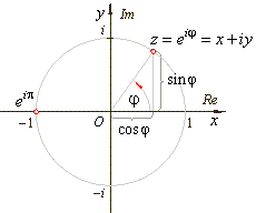 Unit circle in Complex number system
The math behind the $i, j, k$ multiplication are as follows:
\[i^2 = j^2 = k^2 = ijk = -1 \\ ij = -ji = k \\ jk = -kj = i \\ ki = -ik = j \\\]In the above equations, except for the first one, the term wise product is quite similar to the cross-product in vector algebra! Mind you, these are definitions. So don’t go around questioning them.
 Lord Kelvin’s take on quaternions
Now how are quaternions useful? Well they come in handy when you’re working with coordinate transformations or body rotations. In robotics this is a very important topic: transformations. Usually there are several important components/links in a robotics system. This includes: the inertial world, robot’s base link, other components of the robot such as camera link, sensors like IMU and LiDAR, wheels, flaps (in an aircraft), propellers (in a quadrotor), GPS map frame, etc. You would want to know the orientation of these links in relation to each other; eg., orientation of robot base link with respect to world. There are two important things to remember in this case:
- Each of these links have a unique coordinate frame attached to them
- Orientation of a link (frame) B with respect to another link (frame) A is written like so: $R_{A}^{B}$ eg., $R_{world}^{robot}$
Now all this definitions call for a small terminology. Please bear with me :)
- When you want to describe the robot that rotates in real life wrt to the stationary world frame, it’s called a body rotation: $R_{world}^{robot} \rightarrow R_{world}^{robot’}$
- When you want to describe the robot from a frame of reference other than the world, let’s say map coordinates (from GPS), then it’s called coordinate transformation: $R_{world}^{robot} \rightarrow R_{map}^{robot}$
For all intents and purposes, there is some common change happening in either of these two cases. So I will be using these terms interchangeably in the rest of the post.
In real life, we deal with 3D rotations/transformations. Now that we know what we are dealing with, how do we describe a rotation? We have four ways of doing this. We can use one of:
- Rotation matrix
- Euler angles
- Quaternions
- Angle-axis (not discussed here)
These four representations are interchangeable; ie., you can switch from one representation to another! Let’s take a look at these three representations:
NOTE: If you want the full math behind these things I suggest you to go through this detailed tutorial.
Rotation matrix
A 3D coordinate frame is usually denoted by three orthogonal unit vectors, $i, j, k$ along the three axes $x, y, z$. Jumping straight to math here, the rotation matrix that represents a rotation (duh) from frame ‘A’ to frame ‘B’ (or orientation of frame ‘B’ wrt frame ‘A’) is be given by,
\[R_{A}^{B} = \begin{bmatrix} i_A . i_B & i_A . j_B & i_A . k_B \\ j_A . i_B & j_A . j_B & j_A . k_B \\ k_A . i_B & k_A . j_B & k_A . k_B \\ \end{bmatrix}\]In the above representation, the terms are nothing but dot products of the unit vectors of the frames. Let’s say you want a transformation from a xyz-NED (North East Down) frame to xyz-ENU (East Norht Up) frame. Here, we can clearly see that $x$ and $y$ axes are interchanged and the $z$ axis is negated. So the matrix would be as follows:
\[R_{NED}^{ENU} = \begin{bmatrix} 0 & 1 & 0 \\ 1 & 0 & 0 \\ 0 & 0 & -1 \\ \end{bmatrix}\]Inverse of this matrix would give us rotation from ENU to NED. Psst, the inverse in this case is the same matrix because all you need to do is to again switch the $x$ and $y$ axes and negate the $z$ axis. Pretty simple huh? In fact Rotation matrix follows several nice properties such as,
- Inverse of a rotation matrix is the same as it’s transpose (how neat?!)
- Determinant of a rotation matrix is 1
- Rotation matrix is orthogonal, meaning you get zero when you multiply a row(column) by another row(column)
If your matrix doesn’t follow these properties, then it’s not a rotation matrix at all :p
Euler angles
Isn’t rotation majorly concerned with angles and stuff?? Welcome to Euler angles. Any 3D rotation can be constructed by a sequence of three rotations about the three axes $x, y, z$. However the order of these rotations matter a lot! A rotation of 30 degrees along $x$-axis followed by rotation of 40 degrees along $y$-axis is NOT the same as 40 degrees along $y$ followed by 30 degrees along $x$!
Also in Euler angles, you have two possibilities:
- Extrinsic rotations: Axes about which you rotate remain stationary
- Instrinsic rotations: After the rotation along the first axis, the consecutive rotations are along the now modified/rotated axes
Conversion between these two conventions (and their proof) can be seen here and is pretty easy to follow. Spoilers: intrinsic rotation can be obtained by reversing the order of extrinsic rotation (given the rotation angles are the same).
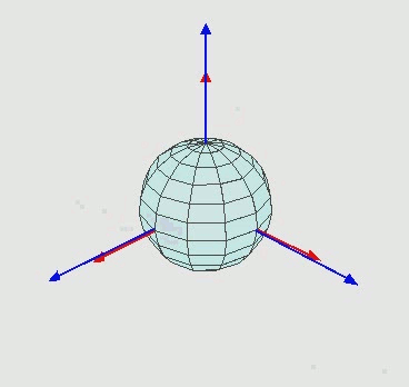 Intrinsic Euler angles rotation z-x’-z’’
Let’s say you perform an intrinsic rotation by rotating about say $z$-axis first, then about the new $x$-axis, then finally again about the latest $z$-axis (in the figure above). This is denoted by $z-x’-z’’$ (look at the primes for changing axes). If you perform an extrinsic rotation then it’s denoted by $z-x-z$ (no primes for stationary axes).
Not considering the distinctions of extrinsic and intrinsic, there are 12 such possibilities $(x-y-x, \ z-y-x, \ y-z-y , \ etc.)$. (Why not 27? You know, 3 times 3 times 3. Guess how ;)) If you use all the three axes like $z-y-x$, then it’s called Tait-Bryan angles (don’t fret, it’s just a different name). In flight dynamics, $z-y’-x’’$ convention is commonly used (aka yaw, pitch and roll; in that order).
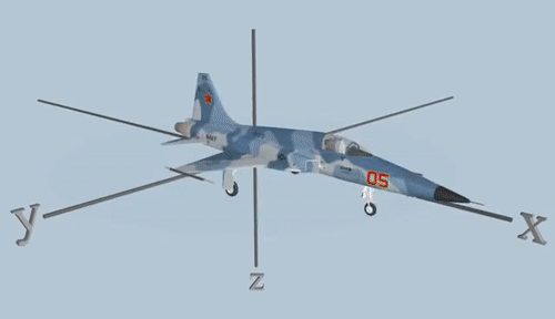 Intrinsic Tait-Bryan angles rotation z-y’-x’’
In order to convert them to a rotation matrix, we can compose the following:
\[\begin{aligned} R(euler) &= R_{z(\psi)} R_{y(\theta)} R_{x(\phi)} \\ \\ &= \begin{bmatrix} c \psi & -s \psi & 0 \\ s \psi & c \psi & 0 \\ 0 & 0 & 1 \\ \end{bmatrix} * \begin{bmatrix} c \theta & 0 & s \theta \\ 0 & 1 & 0 \\ -s \theta & 0 & c \theta \\ \end{bmatrix} * \begin{bmatrix} 1 & 0 & 0 \\ 0 & c \phi & -s \phi \\ 0 & s \phi & c \phi \\ \end{bmatrix} \end{aligned}\]where $c = cos$ and $s = sin$. It’s a brave new world :D try doing this multiplication yourself.
Quaternions
We already have rotation matrix and euler angles to represent rotations. Why do we even bother with another representation?? Well the answer lies in precision and efficiency. Euler angles are prone to a phenomenon called gimbal lock when the innermost axis and outer axis coincide and we lose a degree of freedom. This leads to some weirdass rotations and was a big problem during Apollo 11 mission. Rotation matrices on the other hand are more expensive to store (9 values when compared to 4 values of quaternions) and also computationally expensive (duh). Quaternions don’t have gimbal lock problem of euler angles and are efficient compared to rotation matrices.
In order to get the representation of a point $p (x,y,z)$ in space after a coordinate transformation (or rotate a point $p$ attached to a body), we write it as follows in these three representations:
\[\begin{aligned} Rotation \ matrix: p' &= R_{A}^{B} * p \\ Euler \ angles: p' &= R_{BA z(\psi), y(\theta), x(\phi)} * p \\ Quaternions: p' &= q_{A}^{B} * p * q_{B}^{A} \\ \end{aligned}\]NOTE: Quaternions inverse: If $q = (q_w + q_xi + q_yj + q_zk)$ then $q^{-1} = (q_w - q_xi - q_yj - q_zk)$.
Here, for the rotation matrix and euler angles there’s only a single left multiplication. However, the quaternions have an inverse (notice the A and B switch) right multiplication as well. What is going on?? There’s a reason for doing this; check out this video to learn more.
When doing quaternion multiplication for rotation of a point, we write $p$ as $p = (0 + p_x i + p_y j + p_z k)$. Writing $p$ like this makes it a “pure” quaternion since the real part is zero. Sandwich multiplication by a quaternion $q = (cos \ \frac{\alpha}{2} + sin \ \frac{\alpha}{2} (q_xi + q_yj + q_zk))$ like this produces a rotation of angle $\alpha$ about the axis $(q_x, q_y, q_z)$. This is also called an angle-axis representation! Another representation? Lol. But this representation is hardly ever used in practice as combining several rotations with this representation is hard.
Now that we have this going for us, we can equate the right hand terms in the above equations to find the relations between quaternions, euler angles and rotation matrix. Derivations are given in this tutorial. If you’re not afraid of a little math, you can derive them yourself!
Get quaternions from Euler angles:
\[\begin{bmatrix} q_w \\ q_x \\ q_y \\ q_z \\ \end{bmatrix} = \begin{bmatrix} \cos (\phi /2) \cos (\theta /2) \cos (\psi /2) + \sin (\phi /2) \sin (\theta /2) \sin (\psi /2) \\ \sin (\phi /2) \cos (\theta /2) \cos (\psi /2) - \cos (\phi /2) \sin (\theta /2) \sin (\psi /2) \\ \cos (\phi /2) \sin (\theta /2) \cos (\psi /2) + \sin (\phi /2) \cos (\theta /2) \sin (\psi /2) \\ \cos (\phi /2) \cos (\theta /2) \sin (\psi /2) - \sin (\phi /2) \sin (\theta /2) \cos (\psi /2) \\ \end{bmatrix}\]Get quaternions from Euler angles:
\[q_w = \frac{1}{2} \sqrt{1 + R_{11} + R_{22} + R_{33}} \\ q_x = \frac{1}{4q_w} (R_{32} - R_{23}) \\ q_y = \frac{1}{4q_w} (R_{13} - R_{31}) \\ q_z = \frac{1}{4q_w} (R_{21} - R_{12}) \\\]If you want to combine rotations, we just keep left multiplying with the desired rotation entities like below:
\[\begin{aligned} R_{A}^{C} &= R_{A}^{B} * R_{B}^{C} \\ \text{or with quaternions,} \\ q_{A}^{C} &= q_{A}^{B} * q_{B}^{C} \\ \end{aligned}\]Remember the coordinate transformation we talked about before? We want to get the orientation of our robot wrt to the GPS map coordinates like this:
\[q_{map}^{robot} = q_{map}^{world}$ * q_{world}^{robot}\]Obviously we need to know the orientation of the GPS map coordinates wrt to the inertial world coordinates. One thing to keep in mind is that these multiplications are not commutative, meaning $q_1 * q_2 \neq q_2 * q_1$ and that the order of multiplication is very important! I hope this post has shed some light on quaternions and how they are used in rotations/transformations. Fin.